


By Irene Alfred, Boris Rottwinkel, Christian Noelke, Volker Wesling, Stefan Kaierle
Nickel-based superalloys are used extensively in the combustor and turbine sections of aircraft engines due to their ability to withstand temperatures of up to 1100°C, thereby increasing engine efficiency. The microstructure of single-crystal turbine blades show superior creep and fatigue properties when compared to poly-crystal alloys and increase their lifespan. However, the production of such parts remains expensive and extensive as the process involves a thermal gradient to allow for directional solidification to create a single crystal microstructure. Since these parts undergo the most amount of erosion and cracking during their lifetime and no effective repair method exists, these parts must be replaced, which is an expensive process.
Our objective was to achieve a single-crystal clad on a single crystal turbine blade while facing the challenges of maintaining said structure of the substrate as well as the deposit and avoiding solidification cracks. We hypothesized that the combination of laser powder deposition and laser remelting would lead to the reorientation of the polycrystalline area and thereby extend overall single-crystal height. In order to achieve our goals, a diode laser system with a wavelength of 980 nm and a maximum power of 340 W was used. Experiments were carried out on CMSX-4 and PWA 1426 substrates as well as on turbine blades of the latter material.
Laser Cladding
The first step of the process was to carry out a parameter study in order to determine a set of laser process parameters that resulted in tracks that were free of cracks and pores and also did not diminish the crystallographic orientation of the substrate during the process of cladding. In order to do so, the primary laser cladding parameters, namely laser power, laser travel
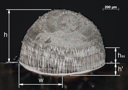
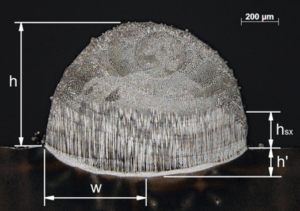
speed and the powder feed rate, were varied and the track parameters shown in the figure below were measured.
The clad height (h) was defined as the height from the surface of the substrate to the highest point, while the single-crystal height, hsx, was measured at the shortest distance between the
surface and the beginning of polycrystalline microstructure. In order to reduce the effect of process instabilities and variations of the melt pool chemical composition, hsx was measured at the
cross-sectional and longitudinal axes. The melt pool depth, h’, and the polycrystalline area, Ap, were also measured, which resulted in five tracks for further testing, the laser parameters
required to create them and the track parameters that were measured.
Laser Remelting
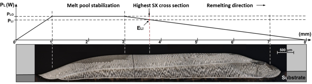
For the process of remelting, we hypothesized that ideal pairs of remelting speeds (vr) and energy inputs (ELI) that resulted in the highest monocrystalline volume would exist. These values were determined by evaluating the results of our power ramp methodology that is depicted in the figure below. The power ramp methodology involved maintaining the remelting speed at a constant value while decreasing the laser power linearly over the course of the track. The laser power was increased to 200 W prior to the start of the track in order to ensure the beginning was not abrupt, after which a short period of constant laser power was maintained to allow for melt pool stabilization prior to the linear drop in power. A descending ramp ensured that unnecessary heat would not be built up in the substrate and disrupt the thermal gradient necessary for the formation of monocrystalline structures.
The remelting process was carried out at 3.3 mm·s-1, 2.5 mm·s-1, 1.7 mm·s-1 and 0.8 mm·s-1 for each of the five tracks. Longitudinal analyses of the microstructure of the tracks were
then carried out. By determining the highest single-crystal cross section and the corresponding laser power, it was possible to determine pairs of vr and ELI values.
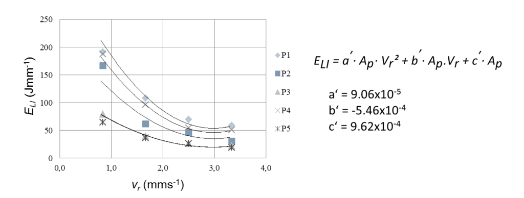
It was determined using the method of least squares that a second degree polynomial equation best represented the relationship between the values. In an attempt to define a single
family of equations that would allow for the determination of ELI using track parameters, the polycrystalline area (Ap) was taken into consideration in the equation and the coefficients a’,
b’ and c’ from the general second degree polynomial equation recalculated. The resultant general equation is as follows (Figure 3):
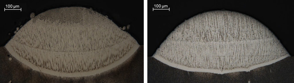
Using the above equation, a set of remelting parameters was calculated and applied to a single track of CMSX-4 and PWA 1426. As is seen in the figures below, it was possible to extend
the height of monocrystallinity past that which was created during the cladding process.
Multi-layer Cladding
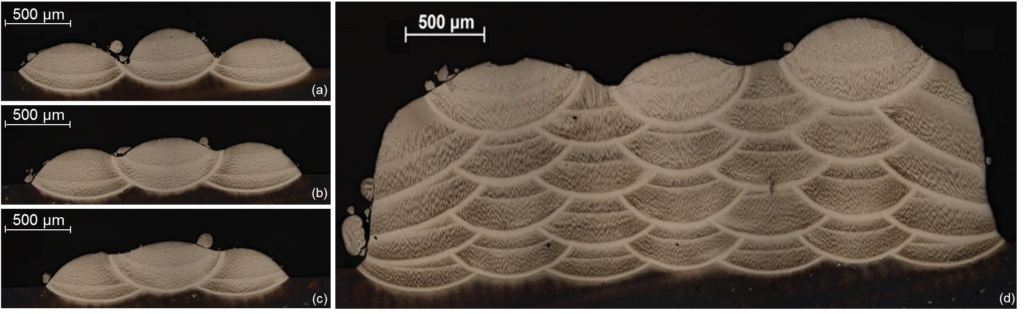
In order to create multilayered structures, the substrate orientation and heat drainage effects had to be taken into consideration. The most common strategy of creating such layers is by overlapping one track with the next. However, this could cause a misalignment of the thermal gradient and the formation of an acute angle between the new track and the substrate, which could lead to the formation of cracks and pores. In order to determine an ideal distance between the tracks, the following values were tested: 1.3 mm, 1.5 mm and 1.7 mm and the
resultant tracks depicted.
At 1.7 mm the space between the tracks is not sufficiently filled and a spacing of 1.5 mm shows a polycrystalline area at the overlap of the tracks that could be susceptible to hotcracking
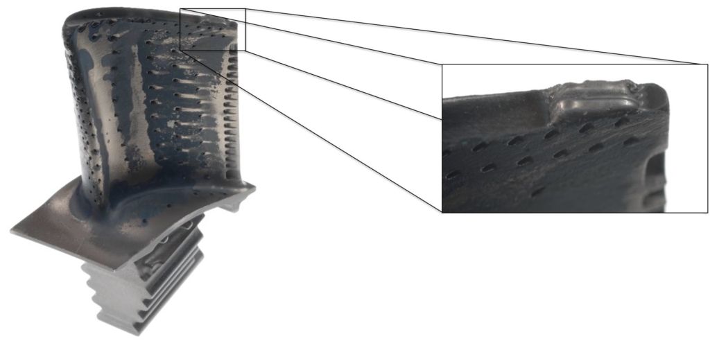
in subsequent steps of the cladding process. Tracks with the spacing of 1.3 mm showed the best results with the gap being filled and the surface creating an ideal substrate for further cladding. The multilayer clad on the right, obtained by the parameters previously deduced, showed a single-crystal structure with a height of 650 μm and a width of 3,700 μm. A complete reorientation of regions that were previously misoriented was also observed. Using the parameters deduced in the previous steps, a process was developed to perform cladding on a turbine blade tip, which
showed no macroscopic cracks as shown below.
Summary and Outlook
While our present and future work seeks to further validate this design of experiments, we were able to show that the processes of laser cladding in combination with laser remelting is a capable
tool for improving and simplifying the formation of large single crystal volumes. It was determined that ELI, the energy input per unit length necessary to remelt and reorient a track increases
exponentially with decreasing remelting speed. We were also able to define a relationship between laser parameters and track parameters during the cladding and remelting processes,
which allows us to predict and calculate said parameters.
This process shows promising results for the repair of single-crystal turbine blades and requires further evaluation with regard to the thermal properties and detailed microstructural analyses of the regenerated parts.