


By Carl Hauser
Introduction
An additive manufacturing method developed by TWI within the framework of an EU-funded project could drastically reduce component manufacturing times.
TWI engineers have been using laser metal deposition (LMD) to produce net shape thin-walled engine casings, aiming to reduce the environmental impact of civil aerospace manufacturing.
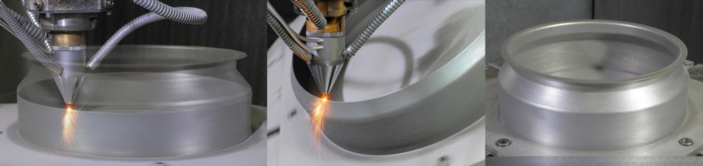
In LMD, a weld track is formed using metal powder as a filler material which is fed, through a coaxial nozzle, to a melt pool created by a focused high-power laser beam. An inert gas carrier transports and focuses the powder into a small area in the vicinity of the laser beam focus (powder-gas beam focus). By traversing both the nozzle and laser, a new material layer develops with good precision and user-defined properties. The application of multi-layering techniques allows 3D structures to be created directly from a CAD model without the need of additional tooling. Historically, coatings and 3D objects deposited by LMD tend to be considered as near net shape.
The focus of the study was an axis-symmetric cylindrical casing with a maximum diameter of 300 mm, a wall thickness of 0.8 mm and a height of 88 mm (see Figure 1). The component is traditionally manufactured from a nickel alloy (Inconel 718), forming a complex geometrical topography requiring specialist tooling, all of which absorbs significant resource (six months lead time) and generates a large amount of waste material when manufactured.
From Design to Manufacture
Two years of development and six months of demonstration activity, led by the team at TWI’s Technology Centre in South Yorkshire, concluded the validation of CAM-style software tools created as a plug in to TWI’s ToolCLAD software: a software package being developed at TWI specifically for the LMD CAD-to-part-manufacturing process. The plug in maps a five-axis vector toolpath with deposition parameters to guide a three-axis coaxial LMD nozzle across a moving substrate manipulated by a two-axis CNC rotary table, creating a novel method of LMD manufacturing.
With precise synchronization of the movements of rotation and tilt of the substrate with incremental movements of the coaxial nozzle (predominantly in the +Z direction), a continuous spiraling weld track can be deposited or ‘grown,’ layer on layer, from out of the substrate. The helical multi-layering technique allows a thin-walled 3D contour to form, which accurately follows the changing directions of the original CAD surface profile (STL file). The process is analogous to a clay pot forming on a potter’s wheel. By allowing the substrate to control movement, rather than traversing the nozzle around a circular path, gives a consistent and regular weld track, and therefore, a good surface finish. Furthermore, the tipping of the substrate to axially align the orientation of the growing wall with the cladding nozzle allows overhanging features to be created without the need to build additional support structures.
A key innovation was the development and use of an adaptive slicing algorithm which automatically varies the numerical slice height (lead distance or pitch) between each helical revolution of the calculated tool path. The magnitude of the change is governed by the orientation of the facet (triangle) normal at the required slice height within the STL CAD model. However, during deposition, the actual build height is maintained at a fixed value to ensure a consistent surface quality. Hence, the adaptive slicing approach modulates the number of layers deposited per unit distance of build height which is governed by the tilt angle of the rotary table. Without this feature, printed parts would have a sizing error in the Z direction.
Modelling Heat Effects to Improve Precision
To assist with the experimental investigations the heat effects during LMD processing were replicated by Finite Element Analysis (FEA). With the utilization of FEA models, the prediction of the shape change of the LMD built casing could be calculated and compared to the target CAD geometry. The results from modelling agreed closely with visual observations, where much of the temperature dependent distortion occurred in the first 15-20 mm of build height. This caused the cylindrical wall to pull inwards. This distortion is linked to the build-up of cylindrical stress distributions during cooling coupled with the thermal shock of depositing the wall onto a substrate held at room temperature. The calculation of the magnitude of the distortion, layer on layer, helped to compensate the wall movement and maintain nozzle alignment on top of the growing wall through appropriate adjustment of the tool path.
Bringing Real-World Benefits
The high integrity of the final part, coupled with the low thermal loading imparted by the process, allowed it to be removed from the substrate with little further distortion. This is evident from the results of geometric 3D scanning. Overall tolerance across the largest diameter was ±250 µ. The wall thickness averaged 0.854 mm with a tolerance of 0.8 mm ±0.1 mm. The surface finish averaged 15-20 µ RA with the higher values centered on the fillet radii; probably because the powder-gas beam focus was not co-located directly on top of the growing wall during continuous reorientation of the table. This created a subtle stair step effect around a curved feature. It is important to note that a final heat treatment step would be necessary to alleviate residual stress that invariably builds up during LMD manufacture.
The LMD manufacture and subsequent dimensional measurement of a combustion casing prototype confirmed that the software and procedures developed in this study were capable of net shape manufacture. Furthermore, the LMD part was proven to have the same geometrical accuracy as a part produced by conventional manufacturing methods. The only difference was surface roughness, which increased from 0.8-1.6 µm to 15-20 µm in the LMD part; although this was still considered acceptable.
The key to the success of achieving the required geometric accuracy and surface finish was minimizing nozzle movement and allowing the substrate to do most of the work. The 7.5 hr build time was a significant reduction over the current six month lead time. However, the LMD productivity rate of 0.1 Kg/hr of deposited powder was considered very low. This can be ascribed to the requirement of wall thickness and surface finish which dictated weld track size and quality. The density of the final part was at least 99.5 percent. The weight of powder material fused in the final part was 750 g and 1.1 Kg of powder was pushed through the nozzle during manufacture, giving a 70 percent material efficiency. Conventional manufacturing routes for the casing (including the manufacture of tooling) generated several 10’s Kg of waste material.
The presented work is now being applied to other demonstrator applications across a range of different industrial sectors. This includes procedures to manufacture geometries with thicker walls, the addition of surface deposited features and parts with larger diameters.
Dr. Carl Hauser is a consultant on Additive Manufacturing and 3D Printing for TWI and would like to thank Neil Preece (TWI, UK) and Loucas Papadakis and Andreas Loizou (Frederick University, Cyprus) for assisting in the experimental work and process modelling.